If the computer is assembled “from scratch” or bought from hand to spare parts, often the system of the system unit is sold with installed power. In other cases, the placement of wires will also not become a big problem. If you are ready to connect yourself, below will be described in detail how to do it correctly.
Placement of a power supply in a computer
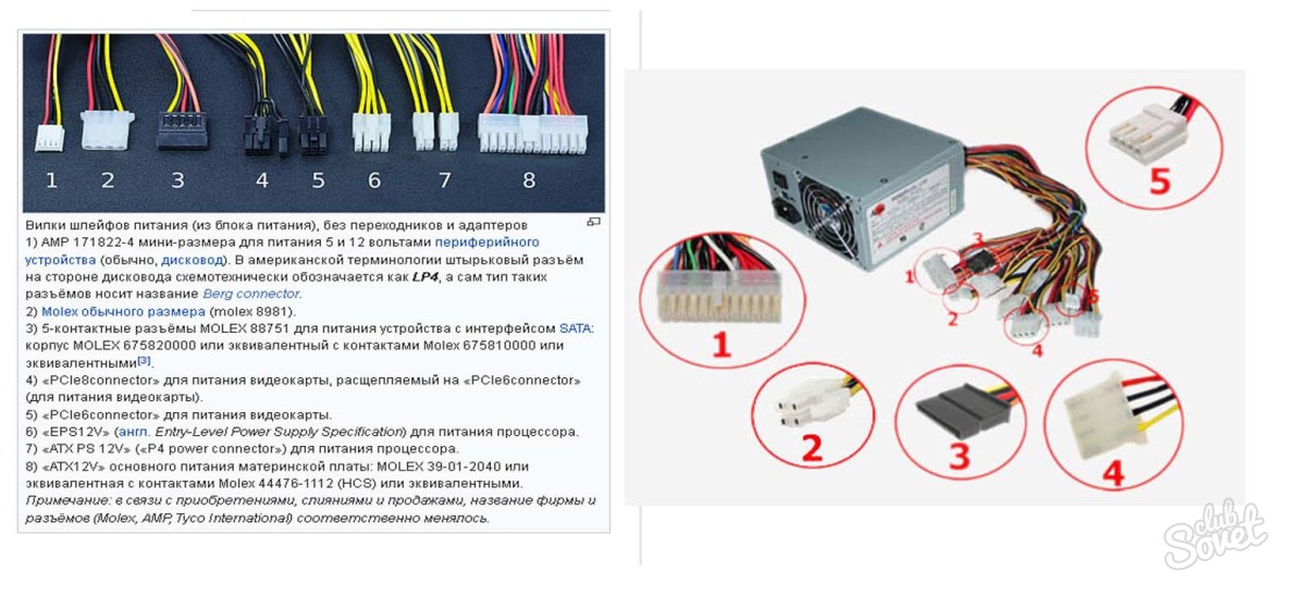
In the physical sense, the installation of the power supply in the body of the system unit is limited to its attachment to the allotted place (top and left) with four bolts. It is extremely difficult to make mistakes here. But what to do with numerous connectors? Let's take a look at them more closely. The standard power supply has:
- The power module for 24 contacts connected to the motherboard and supplies to it (along various lines) of voltage of 5, 3 and 12 volts.
- 4 contact connectors of 12 V. From them will be recorded a central processor.
- Power of the SATA standard.
- The same, for "Molex".
- Connector for the drive.
In order not to make confusion into further explanations, we immediately look at the attached image. The numbers indicate the connectors corresponding to the menu items (as well as an alternative illustration of connectors with an extended description).
Features of connecting the power connectors of the power supply to other components
The main task of the user in the independent connection of modules for powering elements of the system unit is their proper positioning relative to the planting nest. The connectors must be connected smoothly and without unnecessary efforts, to a characteristic click of the latch, if any. If you are not sure of the correct placement, carefully study the connector and the corresponding “landing place” to avoid breakdowns. To power the PC, reboot and built -in speaker button:
- We are looking for a set of wires coming from the power supply. Depending on the manufacturer, they will differ, but the basic principle of work will remain.
- The inscriptions “Power SW” and “Reset SW” on the connectors will be responsible for the functions of the inclusion and reboot buttons on the body. They need to be connected with a group of “pins” on the motherboard marked with suitable abbreviations - for example, PW for Power and Reset. There may not be literal correspondences, we are guided by the meaning of the task. Here you should not be afraid to “burn” something or break (within reasonable limits), you can choose a connector by trial and errors. In addition, in specific cases, this will give space for useful experiments. For example, if the dual -pin “power” is combined with the pins of the reboot, then the PC will turn on precisely by this button.
- Among other elements that are useful to connect by analogy - “Power LED” (for the operation of LEDs on the front panel of the system unit), “HDD LED” (LED, noting the appeal to the Winchester), “PC Speaker” or “Speak” (system speaker) .

The connection of any other components is made in a similar way, but can vary slightly, depending on specific examples. If the connector you need does not leave the power supply, you should look for the appropriate adapter.